FE Beam - Reference Text, Vol. I
- ortwinohtmer
- Dec 23, 2020
- 4 min read
Updated: Dec 24, 2020
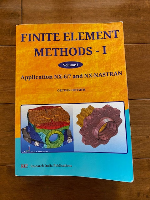
Finite Element Methods - I
Application NX-6/7 and NX-NASTRAN

Since my student years, Mechanical Engineering and Applied Mathematics were always my favorite subjects. Later in my professional life , I selected positions related to the named topics. Therefore , I publish my first Volume „Finite Element Methods I „ after a life-long teaching and research experiences. Six volumes were prepared over the years as manuscripts for different classes :
ME 305, Numerical Methods in Engineering ME 409A, Finite Element Methods I ME 563, Linear Finite Element Analysis II ME 663/763, Nonlinear Optimized Structures and Mechanisms (Nonlinear Finite Element Analysis III) ME 490A, CAD/CAM and ME 495/595, Rapid Product Development ME 677/777, Digital Simulation in Engineering (Finite Element Method, Finite Volume Method, Boundary Element Method)
If you really want to learn how finite element methods work, this book is for you. This text book is easy to read with many examples illustrated.
Those manuscripts have been upgraded every year since 1990. The modification and development of source codes for the Finite Element Program Systems STRUDL, NASTRAN and the CAD/CAM Program System CATIA started already in Germany during my tenure at Messerschmitt-Boelkow-Blohm (MBB) in Munich for sixteen years, and developing codes for “Numerical Methods in Engineering” at the University of Braunschweig for six years as Assistant Professor was a very important learning experience. Therefore many publications and handbooks from that time were published in german language. On that platform I have continued learning, teaching, and researching at CSULB since 1984. My students have been very helpful in correcting the class manuscripts every semester.
I am happy that I waited so long to publish my books because now major developments and changes which have occurred in Finite Element Analysis , Optimization , and CAD/CAM over the last ten years will be incorporated . In 1990 , I wrote (see course description for ME 677/777- Digital Simulation - in the catalog): “...optimization of heat transfer-, fluids-, electrodynamics-, and structural problem solutions .” Due to standards today , the mentioned simulations were not really integrated , but they are completely integrated design tools today . The p and h versions in Finite Element Meshing and adaptive meshing are important new developments in fracture mechanics, but automatic meshing based on Solid Modeling as the core communication cornerstone of concurrent engineering represents the real integration of CAD/CAM, Animation and Simulation. The integrated design process is graphically represented below.
You will find this text book is amazing. It will be an excellent reference source for your engineering career.
The analysis techniques of mechanical engineering are now more closely related to the whole design process , as depicted below, for the solid model of a brake system . NX-IDEAS , NX-NASTRAN And NX-6/7 form now an integrated Software System to solve the CAD/CAM , Finite Element and Finite Volume problems , using the same menu-driven syntax . In special cases , the STRUDL- , NASTRAN- , ANSYS -, and ABAQUS-Input can be created automatically based on Solid Modeling and Meshing using the NX- Software.
It is well known that for 2-D and 3-D elements the approximation of the Finite Element Method converges with the refinement of the FE-Mesh against the unknown exact solution (Ritz Method, 1910).For Structures composed of l-D elements (members, beams, trusses, and frames) the Finite Element Formulation represents the simplest exact solution method because of banded and symmetric linear systems of ordinary differential equations. The so-called Structure Stiffness Matrix (Coefficient Matrix) is banded and symmetric. The computing time for the solution of linear systems of equations (Gauss and Cholesky) via elimination increases linearly with the size of the Stiffness Matrix but increases quadratically with the bandwidth of the Stiffness Matrix. The “breakthrough” in Finite Element Technology is that in NX- IDEAS the boundary conditions, loadings, material constants and physical properties are specified for vertices or edges or faces of the Solid Model before meshing. The graphical results are obtained for one mesh size then the solution set is deleted and the automatic meshing of the solid is repeated with a refined mesh. The files for the boundary conditions, loading etc. are always automatically adapted to joints, edges, surfaces, and elements. Now it is very easy for a design-team to estimate the quality of the approximations for displacements and stresses. With a refinement of the mesh the solution converges against the unknown exact solution if “standard” conditions are specified and no “numerically ill-conditioning effects” are occurring.
In the past Fluid Flow Analysis was not integrated due to several difficulties. The Finite Volume Method was not applied or created . Recent publications however indicate that any complex analysis will use Finite Volume Approximation with implicit “Time Differencing” as the Common Analysis Tools. The second integration tool is represented via NURBS (Non-Uniform Rational B-Splines), which is currently the standard tool for Solid Modeling. Curved beam and shell-elements have to be modified based on NURBS ,to match the created NURBS-Mesh-Surface. Similarly, the Finite Volume 3-D cells, blocks with plane surfaces, 2-D cells, and quadrilateral planes with straight edges have to be rewritten based on NURBS. These elements need to be rewritten in order to match the created NURBS edges or surfaces as a boundary condition (the surface of a Fillet for example). (NURBS specified as curved shell Finite Elements). Today physical properties are specified for the solid model prior to meshing. Since the accuracy of the Finite Element Analysis and Finite Volume Analysis improves with the refinement of the mesh, the analysis must be performed for several mesh sizes. Now this process, including the associated graphical representations and the parameter checks, can be executed nearly automatically. For example the solid model of a torus can be subtracted from a block to get the mold for a fluid flow analysis via the Finite Volume Method. After meshing the mold, the flow analysis menus are applied in NX-6. The mesh can also be converted to an MSC-NASTRAN-DYTRAN input for analysis. At the MSC World Users Conference in 1995 I presented the paper “Extending MSC/DYTRAN for the Numerical Solution of the NAVIER STOKES EQUATIONS”. With NX-6 the software is now available , to solve Thermodynamic and Fluid Flow Problems.
FE Beam Course Presentation:


Comments